Shopping Cart: 0 Items

Mitee-Bite Dyna-Force Clamps

Brand: Mitee-Bite CNC Fixture ClampsMitee-Bite CNC Fixture Clamps
CAD105.62 EA
Select
Cost: CAD105.62 EA -
Add to cart

Dyna-Force® Clamps

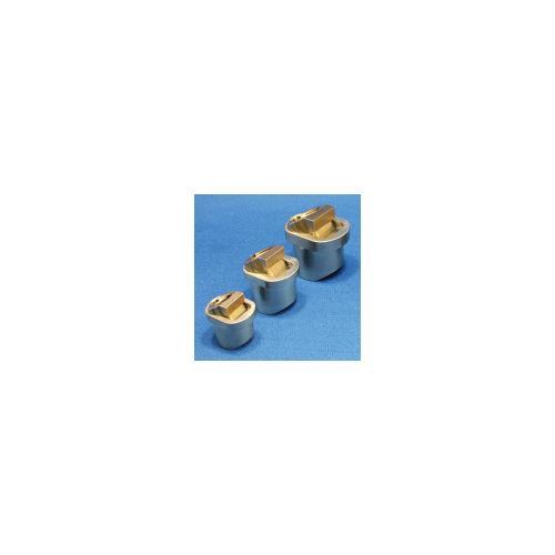
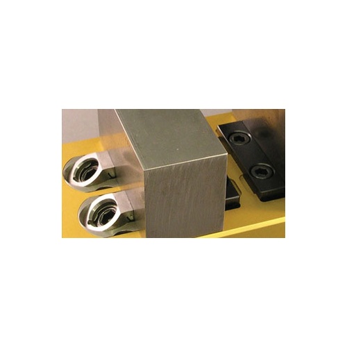
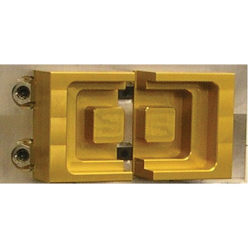
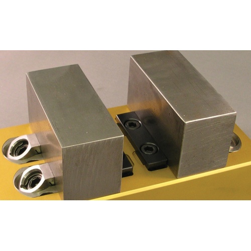
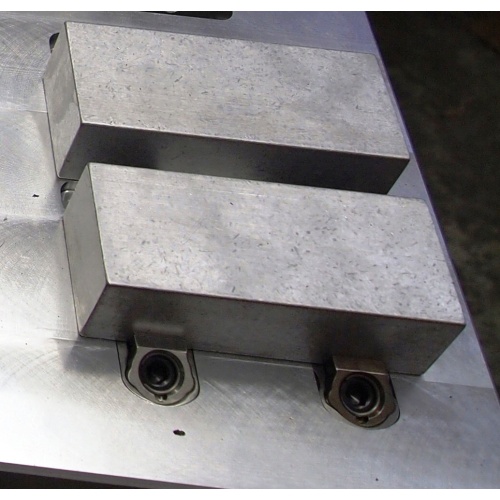
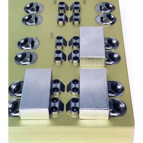
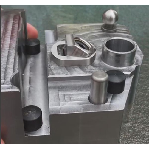
The majority of the Dyna-Force® clamp is below the surface of the fixture which provides excellent clamp support and makes for a very low profile. The clamp jaw slides on an angle for positive downforce.

The clamp jaw is available with smooth or serrated faces.

The support surface of the Dyna-Force® clamp can be installed flush with the fixure plate or raised to hold the workpiece off the fixture, enabling drill-through.

  • Incredible Clamping and Hold Down Power
  • Low Profile, Compact Design
  • 17-4 PH Stainless Steel
  • Smooth or Serrated
  • Stainless steel screws and retaining rings are available for EDM applications

PATENT NO. 5964458

Metric

Part
No.
 Clamp Jaw†
& Hardiness
A*BCDEF
Min
G
Optimum

Max
Clamp
Travel
Drive
Screw
Key
Size
Max
Torque
Holding
Force
Replacement
Insert**
28314
28318
  Smooth 34RC
Serrated 44RC
20.00 24.90 19.00 19.90 4.50 13.50 3.25 5.00 6.75 2.0 M6x12mm 5mm 7.3 (Ft/Lbs)
9.9 (N.m)
2,000 (Lbs)
8896 (N.)
28480 (smooth)
28482 (serrated)
28320
28322
  Smooth 34RC
Serrated 44RC
25.00 29.90 24.00 24.90 5.00 15.00 4.50 6.50 8.25 2.2 M8x16mm 6mm 17.6 (Ft/Lbs)
23.9 (N.m)
2,600 (Lbs)
11565 (N.)
28484 (smooth)
28486 (serrated)
28324
28328
  Smooth 34RC
Serrated 44RC
30.00 37.90 29.00 29.90 7.00 20.00 4.50 7.50 10.75 3.8 M10x18mm 8mm 35.3 (Ft/Lbs)
41.9 (N.m)
3,200 (Lbs)
14234 (N.)
28488 (smooth)
28490 (serrated)
†Smooth jaw only will have relief cut
*Body diameter
**Includes screw and retaining ring

Dyna-Force® Installation

  • Bore ℄ of the hole "L" distance from edge of workpiece.
  • Drill and tap "H" to mount clamp in pocket.
  • Machine counter bore if recessing clamp into fixture.
  • Provide a back stop to locate the part.
NOTES:
  • "N*" – To have rest pad flush with fixture, use the dimension provided. To have the
    rest pad above the fixture surface, reduce the depth accordingly.
  • For dimensions I and J, use a tolerance of +.1/-0mm. For dimension L and O,
    use +.1/-.1mm.

Height of Jaw in Relation to ℄ of bore
from edge of workpiece.

Height of Jaw
G
20mm
L
25mm
L
30mm
L
3.25 5.91    
3.50 5.77    
3.75 5.62    
4.00 5.48    
4.25 5.33    
4.50 5.19 6.81 8.78
4.75 5.05 6.66 8.63
5.00 4.90 6.52 8.49
5.25 4.76 6.37 8.35
5.50 5.61 6.23 8.20
5.75 4.47 6.08 8.06
6.00 4.32 5.94 7.91
6.25 4.18 5.80 7.77
6.50 4.03 5.65 7.62
6.75 3.89 5.51 7.48
7.00   5.36 7.34
7.25   5.22 7.19
7.50   5.07 7.05
7.75   4.93 6.90
8.00   4.78 6.76
8.25   4.64 6.61
8.50     6.47
8.75     6.33
9.00     6.18
9.25     6.04
9.50     5.89
9.75     5.75
10.00     5.60
10.25     5.46
10.50     5.31
10.75     5.17

Example: 20mm clamp when CL of bore is 4.90mm from edge of workpiece
(L – see drawing on left): jaw height is 5.00mm

Part NumberHIJKLMNO
28314 M5 or 10-24 25.00 20.00 6.00 4.90 5.00 4.50 20.00
28318 M5 or 10-24 25.00 20.00 6.00 4.90 5.00 4.50 20.00
28320 M6 or 1/4-20 30.00 25.00 6.50 5.65 6.00 5.00 25.00
28322 M6 or 1/4-20 30.00 25.00 6.50 5.65 6.00 5.00 25.00
28324 M8 or 5/16-18 38.00 30.00 8.00 7.05 7.50 7.00 30.00
28328 M8 or 5/16-18 38.00 30.00 8.00 7.05 7.50 7.00 30.00

Contact Us

Lockhart Logo


  • Vancouver Island, BC, Canada
  • 250-715-7290
  • Need support? Click the envelope below!

Join our Community

Lockhart Tactical
X